HySpex
Geology Workstation
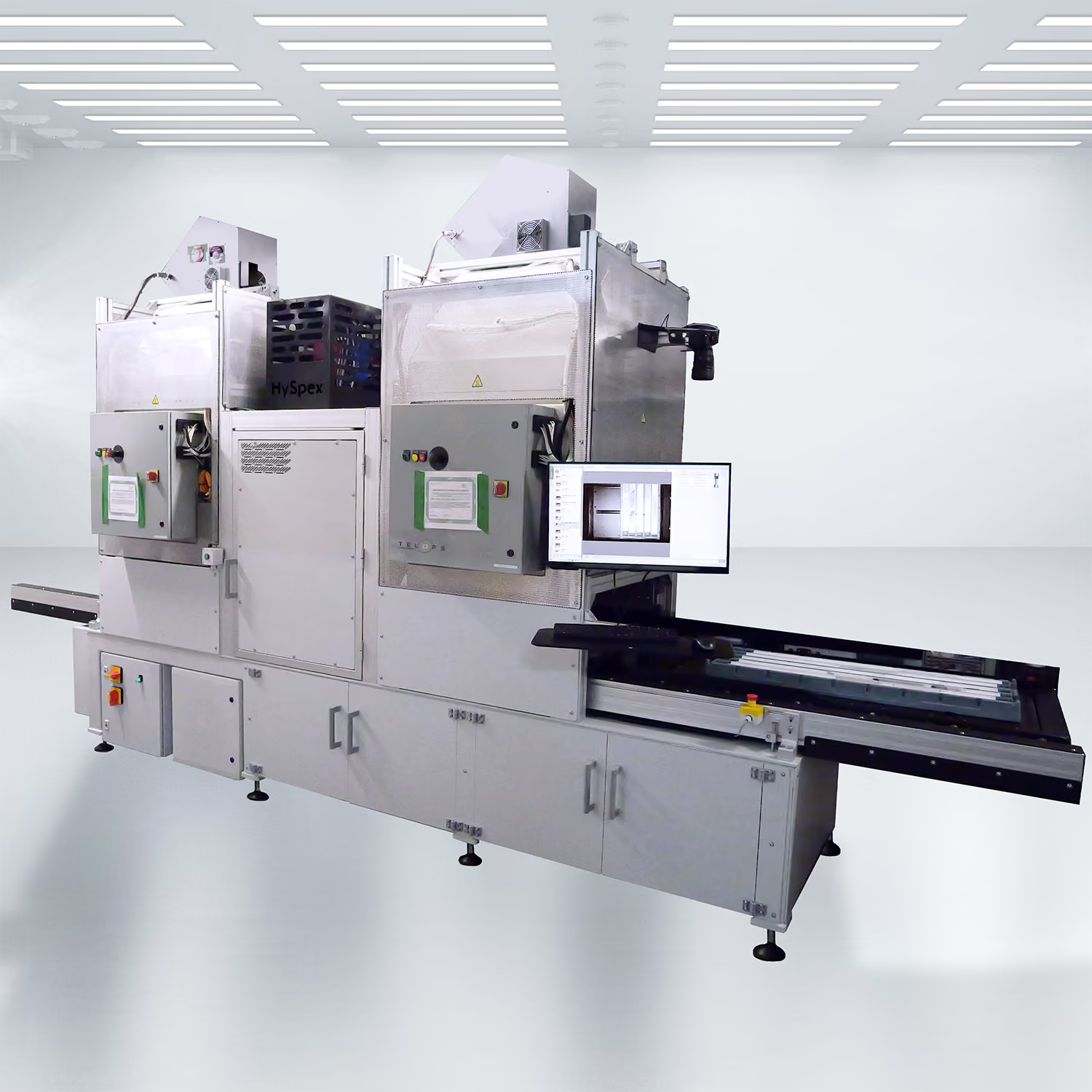

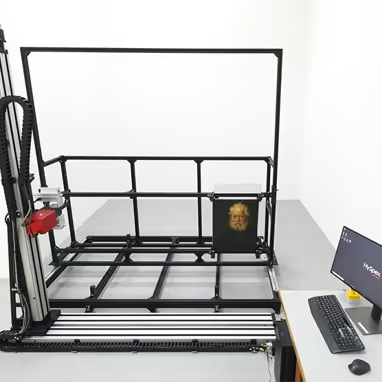
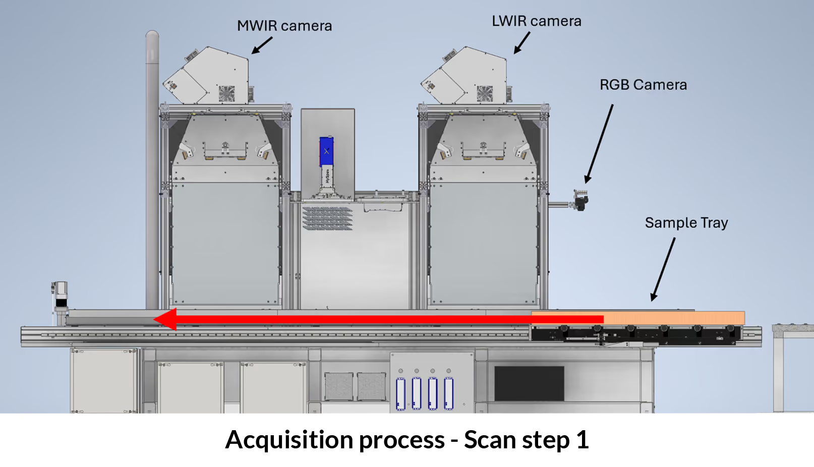
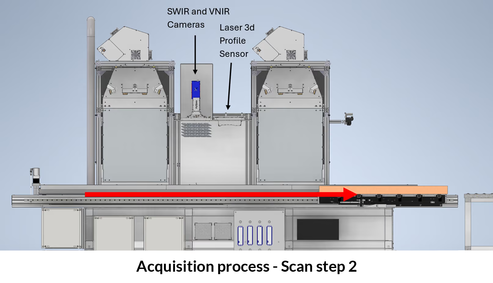
The HySpex Geological Workstation incorporates HySpex VNIR and SWIR cameras, as well as Telops MWIR and LWIR cameras for scientific-grade hyperspectral imagery. The system is designed to be easy to use, allowing you full control over your data, analysis, and results.
Real-time interpretation and visualisation of the scanned core identifies areas of significance, such as alteration mineralisation, highlighting sections requiring assay or geochemical sampling. The resulting mineralogic interpretation and logs can be exported in common formats and are easily included in other core logging software to enable a comprehensive understanding of the data. It also allows you to revisit and reevaluate your data as needed without incurring extra fees.
Though the workstation is optimised for core boxes, it can also handle drill chip boxes, loose samples, and rock mass.
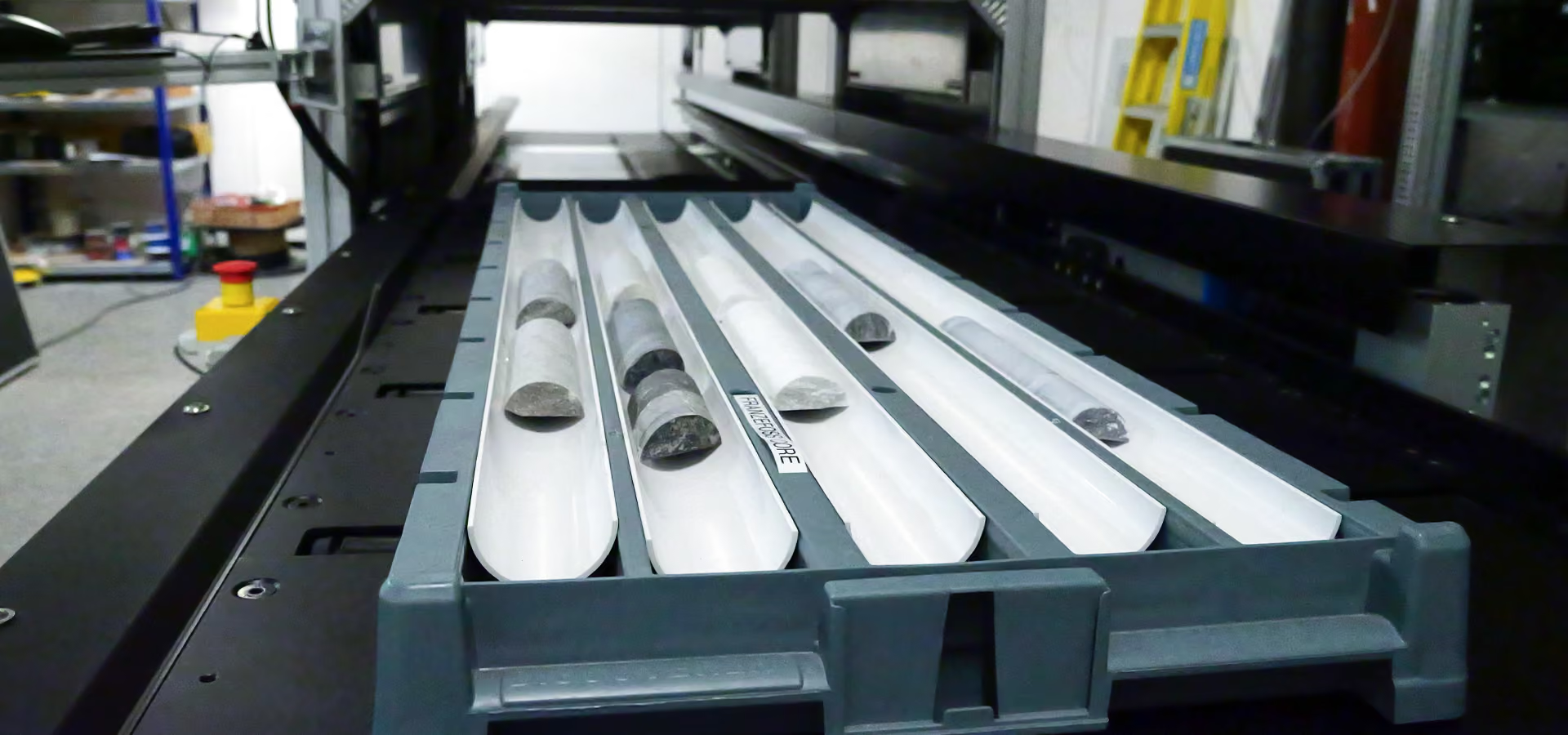
The HySpex Geology Workstation provides:
- High-resolution hyperspectral imagery and RGB data
- Drill-core optimised system
- 3D profiler to correct for varying viewing and illumination geometry
- Real-time mineral analysis capabilities
- Work with your own data
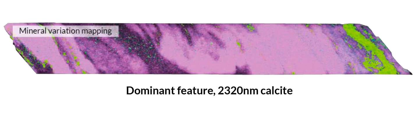
- Map mineralisation phases within the core
- Log and export mineral and lithology maps
High-res core visualised in the Breeze Software
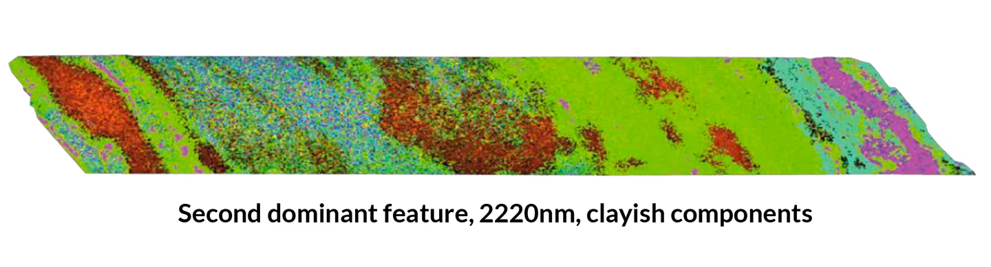
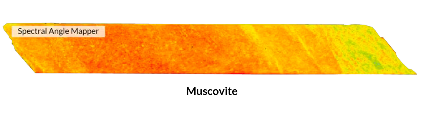
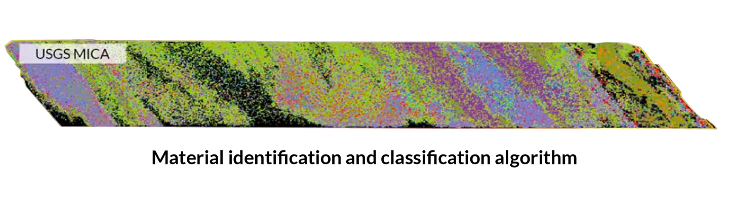
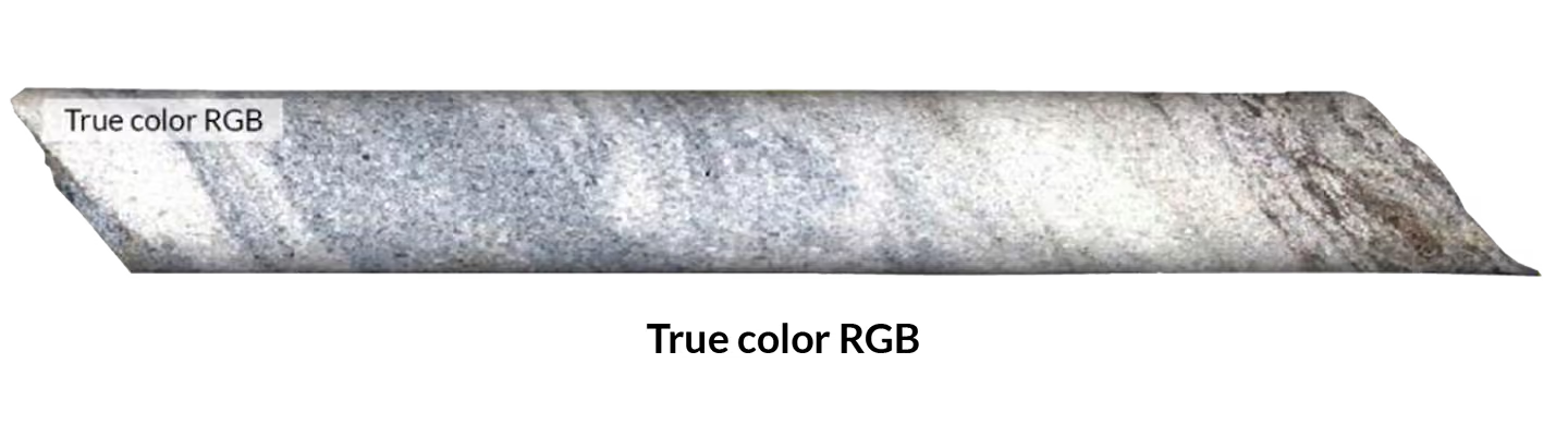
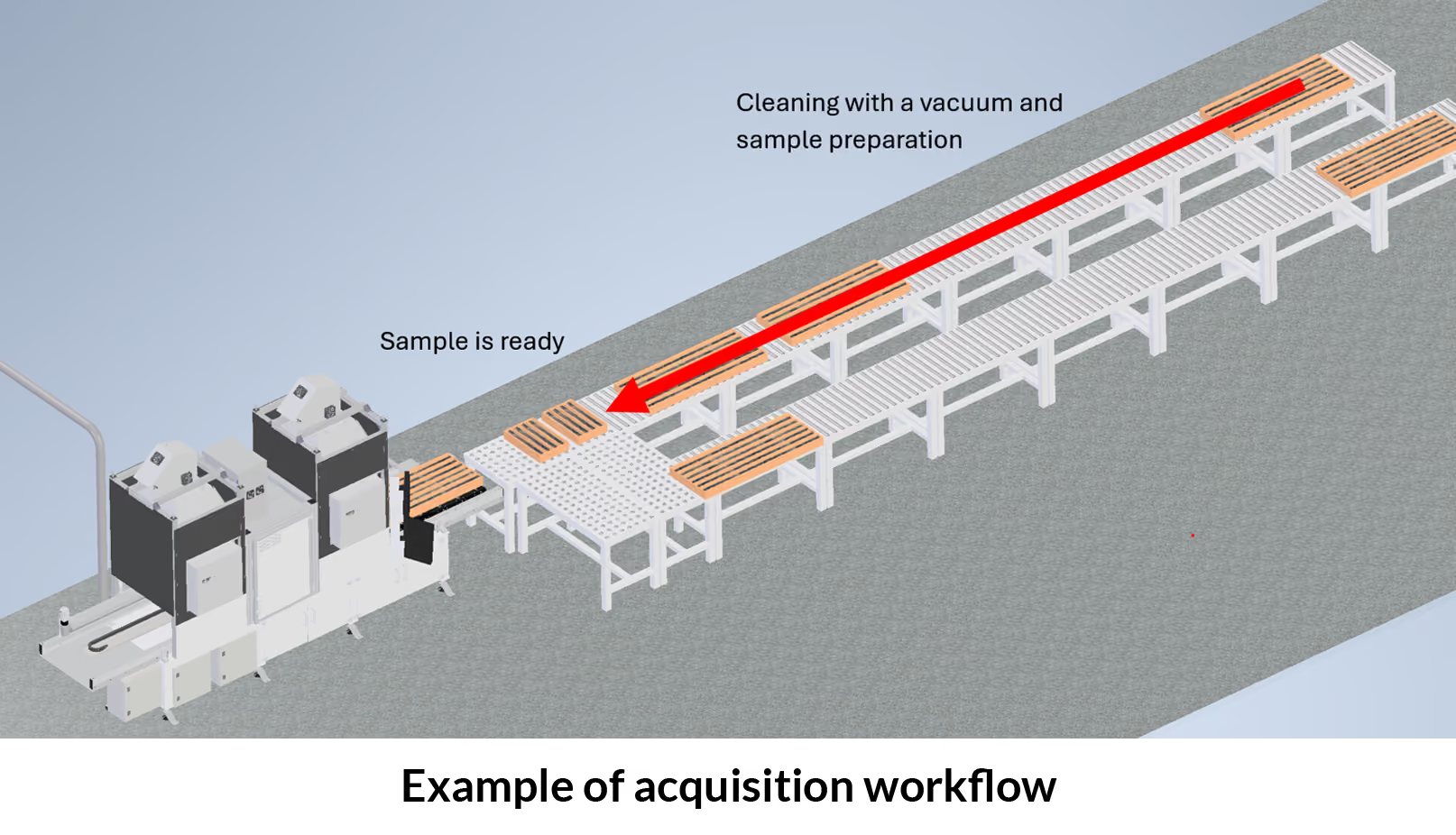
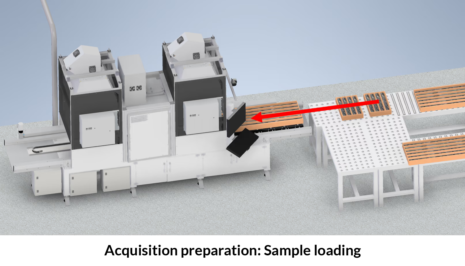
The Acquisition Process
Main Specifications (VNIR+ SWIR)
Main Specifications (MWIR+ LWIR)
1 User-selectable by software, between 2cm (-1) (~3.2nm @ 4 microns) and 64 cm (-1) (~50nm @ 4microns) resolution is typically recommended for MWIR core scanning
2 User-selectable by software, between 2cm (-1) (~20nm @ 10 microns) and 64 cm (-1) (~640nm @10 microns) resolution is typically recommended for LWIR core scanning.
3 User-selectable by software, between 28 and 896; 56 spectral bands is typically recommended forMWIR core scanning
4 User-selectable by software, between 10 and 320; 40 spectral bands is typically recommended forcore scanning
5 The dynamic range is expressed for a specific wavelength as the ratio between the maximumradiance the camera can handle and the minimum detectable change in spectral radiance at thatwavelength, which corresponds to a signal-to-noise ratio (SNR) of 1.
6 It’s possible to reduce the spectral resolution or increase the measurement time to achieve higherSNR.
7 For recommended operating parameters; faster measurement rate is also possible.